Poster presentation: A new approach
to the theory of stress and deformation
based on the theory of potentials

This page contains the text of a poster which I have shown on several conferences. It contains the following sections
  • a mathematical proof that the Cauchy stress tensor does not exist,
  • a physical argument to the effect that the entire theoretical framework of continuum mechanics is unsuited to do justice to the nature of elasticity and stress as a physical phenomenon,
  • an abbreviated outline of the approach I propose,
  • some predictions made with the new approach.

  Cauchy stress theory at variance with Gauss Divergence Theorem

The thermodynamic definition of pressure

                P = U/V                (eqn.1)

or P = DU/DV in integrated form is an explicit statement of the fundamental requirement of potential theory: in a given state U, the ratio of mass in a system to its potential is scale-independent.

The thermodynamic equilibrium condition is Psyst + Psurr = 0. Forces are acting on the system from the surrounding, and vice versa; that is: there are two independent groups of forces with opposite sign in the sense that they are directed either inside or outside.

                thermodynamic equilibrium

The two groups must balance. Thus the equilibrium condition translates into

          ò fsyst × n dA + ò fsurr × n dA = 0, or fsyst + fsurr = 0         (eqn.2)

where f is the source density. The Cauchy theory is based on the assumption that the ratio P = |f|/A ® const as A ® 0, whereas potential theory holds that the ratio P = U/V ® const as V ® 0. Can both conditions hold together?

The source density f in the divergence theorem

                ò f × n dA = ò Ñ × f dV = f                (eqn.3)

is proportional to mass. In a continuum of mass, f is therefore a linear function of the integration limits of the RHS, and Ñ × f = const. If r = |r| is the magnitude of the radius of the thermodynamic system, V µ r3 and
A µ r2. Since LHS is a surface integral, but RHS is a volume integral, it follows that |f| in LHS must be a linear function of scale, i.e.

                |f|/|r| = const.                 (eqn.4)

Thus if V ® 0, f vanishes with r: the ratio |f|/A ® ¥ as V ® 0, but the ratio U/V = P is constant. The Cauchy stress theory assumes that |f|/A approaches a finite value as V ® 0.

Therefore the Cauchy theory is at variance with the divergence theorem. The Cauchy stress tensor does not exist.

The Newtonian definition P = |f|/A is not not applicable in thermodynamics. The Newtonian definition applies to free planes whereas the divergence theorem and P = U/V consider a closed plane. Free planes divide space into top/bottom, left/right, front/back; only a closed plane divides space into inside/outside. Cauchy's approach to stress never distinguished system and surrounding, it is incompatible with the properties of a thermodynamic system.


Newtonian theory unsuited for continuum mechanics and thermodynamics

The basics of continuum mechanics were outlined by Euler in the mid-18th century. He adapted the concepts of Newtonian mechanics, the only one available at his time, which was conceived to understand celestial mechanics. Its main tools are

  1. the equation of motion f = ma, which is the Newtonian definition of force,
  2. the Newtonian definition of work = force times distance, w = f × x,
  3. Bernoulli's energy conservation law, Ukin + Upot = const.
In physics, one cannot choose concepts at random. Choice of a particular concept implies a lot of context. Can Newton's tools be indiscriminately applied to continuum mechanics? Consider:
  1. The Newtonian force definition employs the inertial mass, measured in [kg]. It is thus implied that work is done against inertia, either by displacing a discrete body of mass m in empty space, or by accelerating it. Therefore f = ma refers to a velocity potential.
  2. Newtonian work is path-independent in Euclidean space, i.e. the 3D-space we live in.
  3. Bernoulli's law, the energy conservation law of classical mechanics states: the energetic state of a system undergoing a process in line with Newtonian physics is invariant by definition.
Are there alternatives? Consider thermodynamics:
  1. Mass is dimensionless in thermodynamics and measured in Mol because the thermodynamic potential must be scaled per atom. Thermodynamic work is done not by acceleration against inertia but, e.g., by changing bond lengths in solids.
  2. Thermodynamic work is path-independent in PV-space, the energetic plane.
  3. Thermodynamics is the physics of changes of state, that is: the energetic state of a system is variable by definition. Its energy conservation law is the First Law: dU = dw + dq.
What is the physical nature of an elastic deformation?

The buildup of an elastic potential is a change of state: work is done on a system. Therefore, its proper theoretical treatment requires an equation of state, not an equation of motion, and work done is related to PdV-work, it is not Newtonian work.

None of this is reflected in any way in present-day continuum mechanics where the elastic potential for a volume-constant deformation is zero by definition. This is wrong by nature.

Thus, the theoretical framework of classical continuum mechanics is unsuited to properly deal with the physical reality of an elastic deformation which represents a change of state. Two profoundly different energy conservation laws are thoroughly mixed up.

Euler passed on in 1783. In the following year, Lagrange discovered vector fields and founded field theory. The nature of changes of state was only understood in 1842 when the golden age of thermodynamics began. Continuum mechanics, however, the physics of anisotropic changes of state, remained solidly stuck in the philosophy of the 18th century. It is obsolete by 200 years.


A new approach to continuum mechanics

A new approach to deformation theory must consider the nature of elastic deformation as a change of state. Thus an equation of state is required.

1. Solids have a much smaller molar volume than gases because of internal bonds. Thus they are said to have an internal pressure. An increase in external pressure must therefore be scaled to the internal pressure of the solid. An equation of state is proposed

                PkV = z                 (eqn.5a)

where

                k = ln Vmolsolid/ ln Vmolideal gas                (eqn.5b)

and z is solved by the Birch-Murnaghan equation. Eqn.5 is material- independent. For real materials, k is readily calculated; for modelling purposes it suffices to continue with the ideal gas law.

The approach taken here is similar to that of Grüneisen 1908 (see historical paper).

          Bridgman's original data
A material-independent equation of state for solids: Bridgman (1958) compressed the alkali metals to a confining pressure (external pressure) of 100 kbar.
          Bridgman's data recalc
If Bridgman's data are scaled to the internal pressure of the respective substances, his four independent graphs (above) all converge into one single graph. Thus the material-independent equation of state for solids (eqn.5) is supported by experiments.

Bridgman PW (1958) The physics of high pressure. Bell & Sons Ltd, London


2. Boyle's law is written in scalar terms; it must be transformed into vector form:

                PV = const ® fr = const                (eqn.6)

where r = |r| is the radius of the thermodynamic system, and f = |f| is the force acting on the system surface (either fsyst from within, or fsurr from without).

3. Equilibrium can always be assumed to exist in the elastic state because system and surrounding are physically connected through chemical bonds in the solid; these bonding forces need to be taken into account. Disequilibrium is therefore impossible.

4. Both fsyst and fsurr are understood as classical force fields which are derived from potentials (E = material enthalpy, U = some externally controlled potential):

                fsyst = eiEsyst/xi         fsurr = eiUsurr/xi                 (eqn.7)

with the field property tensors

                2E/x2 = Fsyst          2U/x2 = Fsurr                (eqn.8)

such that f = ò Fdr, or simply Fr = f.

Fsurr is the field property tensor for the external force field, it represents the boundary conditions. Fsyst represents the material properties. The two independent fields are then related to one another by means of the equilibrium condition. The result is the stress field.

5. Once the stress field is derived, the equation of state will provide the displacement field: just as PV = const translates into ln (V1/V0) = - DP/P0, the equation of state in vector form yields

                fr = const ® ln (r1/r0) = - Df/f0                (eqn.9)

Thus, stress is treated as an anisotropic change of state. Stress field and displacement field have exactly identical geometric properties as a function of two independent sets of boundary conditions: the externally controlled set and the material properties.


Results (1)
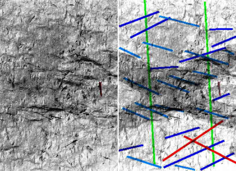
Prediction of fabric property orientations in simple shear zones

The eigendirections (stable directions) of the simple shear stress/displacement field are non-orthogonal. They are correlated with the observed fabric elements:

  • c         contracting eigendirection: parallel to dilational joints that open
              upon unloading, but controlled by residual stress
  • e         extending eigendirection: parallel to S-plane in S-C fabrics
  • R         bisector of small angle: Riedel plane, or C-plane in S-C
              fabrics
  • P         bisector of large angle: P-plane
                simple shear field

The figure shows the predicted properties of a dextral simple shear. These theoretically derived results compare very favorably with natural fabrics.


Comparison
  Left panel: field data from a mylonite (Spessart Mtns, data: K.Weber). Right panel: predicted fabric orientations.

The predicted and observed diagrams are virtually identical, with the exception of the (quartz) grain shape foliation. However, quartz grain boundaries are highly mobile and never reflect the crystal anisotropy. The theory would expect a genetic relation between the extending eigendirection e and e.g., the (001)-plane of mica or the long axes of plag porphyroclasts; their orientation exactly agrees with e.


The theory predicts that the main anisotropy direction of a crystal will find a final orientation parallel to the extending eigendirection e. Crystals can undergo internal dislocation glide only while they rotate externally. Once they reach the maximum, the crystals are in a locked position; that is, dislocation flow alone cannot possibly lead to large-scale deformation. Heterogeneous deformation mechanisms are required.

S-C fabric

Schematic S-C-fabric in a metamorphic shear zone, dextral shear.


Insubric Line 1
Insubric Line 2

S-C-fabric in a lower greenschist facies mylonite, dextral shear. Note dextral offset and discontinuities of color banding across C-planes (red). S-layering outlined by color banding gently rotated against overall sense of shear between C-planes. Yellow: macroscopic foliation. Insubric Line/Sesia Zone, Val Strona, Italy.


New England 1
New England 2

Roughly developed S-C fabric in a fault near the brittle-plastic transition, dextral shear. Black: shear zone boundaries; blue: compositional layering and local foliation, S-plane; red: discontinuities, C-plane. Rhode Island, USA.


Lipari

Simple shear in a subrecent obsidian flow. Upper layer consisting of black glass contains abundant bubbles; lower layer (reddish-tan) partly crystallized. Upper layer developed viscous drag, lower layer developed cracks. Both drag and orientation of cracks indicate dextral shear. Crack orientation correlates with contracting eigendirection c in panel above. Lipari Island, Italy.


Results (2)
Comparative energetics of pure and simple shear

The theory predicts that

  • elastic simple shear requires ca. 11% more energy per unit strain than pure shear.
  • plastic simple shear requires ca. 30% less energy per unit strain than pure shear.
This should result in decay of pure shear into conjugate simple shear in the plastic field and in substantial strain localization, concentration of plastic deformation, and development of narrow deforming bands surrounded by large, non-deforming regions. This is precisely what we observe.

The strong energetic differences as a function of deformation type are in close agreement with experimental results (Franssen & Spiers 1990).

Franssen RCMW & Spiers CJ (1990) Deformation of polycrystalline salt in compression and in shear at 250-350°C. Geol Soc London Special Paper 54, 201-213

                  deformation energetics

In this figure the predicted simple shear energy is scaled to the pure shear energy = 100%.

Results (3)
Origin of sheath folding in rocks, and turbulence in air/water

3D-model calculations suggest that an elastic plane strain deformation consists of an isotropic contraction (one contracting step in all directions), and an anisotropic expansion such that there is

  • a shortening step parallel to the contracting eigendirection c
    ("the Z-direction"),
  • two stretching steps parallel to the extending eigendirection e
    ("the X-direction"),
  • one stretching step parallel to the intermediate eigendirection
    (the Y-direction).
The terms X-direction and Z-direction are given in quotation signs because they refer to the axes of the orthogonal strain tensor. This is something the reader is familiar with; however, the eigendirections of the stress/displacment field and the principal axes of strain do not coincide in the case of simple shear. The properties of strain are physically irrelevant; what matters are the properties of the displacement field. However, non-orthogonal shortening/stretching directions may be something the reader will first have to get used to.

The net stretch parallel to Y is zero; but what matters is the anisotropic part since the isotropic component does not have eigendirections.

Thus if the material yields, no single crack can resolve the entire stored elastic potential at once. Instead, two failures are required; they have similar probability, but are conjugate to one another.

                3D-effect

View on the XY-plane from above (along Z). (Left) Mid-green: undeformed sphere; dark green: isotropic contraction; light green: final shape due to anisotropic stretch // X (vertical) and // Y (horizontal). (Right) Stretch components only. Two metastable least energy stretch directions (red arrows) are conjugate to one another which become phenomenologically existent if the elastic state of loading is relaxed by irreversible processes, resulting in conjugate joints (blue lines)

An irreversible relaxation results at least in momentary disequilibrium. The balanced system decays into two subsystems with opposite unbalanced rotational momentum about the contracting eigendirection (about Z).

Thus linear structures parallel to Y are metastable.

  • In rocks undergoing plastic flow this should result in reorientation of fold axes into the extending direction.
  • In materials with less coherence (air, water) the imbalanced rotational momentum may find a more forceful expression (eddies, twisters, hurricanes).

In rocks the stress decay instability is also responsible for the occurrence of conjugate structures (e.g. joints). Even S-C-fabric is commonly developed in conjugate sets if viewed from above (i.e. on the XY-plane, the main foliation), resulting at mesoscale in a characteristic rhomboid pattern if moderately developed, and in "oyster shell" structure in advanced state.

Staurolite Schist
Left: Pelitic schist, view on the foliation plane. Dark elongated spots parallel to lineation: staurolite crystals, red: pen for scale. Right: Structural interpretation. Green: stretching lineation; red: two joints; blue: traces of C-planes on main foliation (S-plane) form conjugate sets, symmetric relative to lineation; characteristically, one of the sets (light blue, plunging to right) strongly dominates over the other (dark blue, plunging to left). The strongly developed intersection structures are substructures of C-planes at a larger scale, two of which, again conjugate, intersect in the picture (darker shaded cross). Note rhomboid structure just above pen due to interference of both SC-intersection directions.
Joints (red), traces of C-planes (light and dark blue) and C-planes at larger scale (shaded) are all conjugate, and symmetric relative to the stretching lineation (green). Shear sense: background up, observer down. Gove Formation, Rt.101, New Hampshire, USA.


Wedell ice shelf
Orientation of cracks in ice, Wedell ice shelf, Antarctica; dimensions appx.
30 x 40km. Left: Radar image NASA. Colors indicate ice thickness. The cracks ('leads') open if the ice shelf is stretched parallel to NW-SE direction by steady winds. Right: Black lines with angle taken from blue lines in the graph above; the enclosed angle predicted in the graph fits nearly perfectly on the natural crack configuration.


Results (4)
Origin of dilatancy in elastic deformation

The theory predicts that only perfectly isotropic materials undergoing plane pure shear or axial deformation will undergo volume-neutral deformation. Simple shear and/or anisotropic material properties will result in a volume increase/density decrease.

This phenomenon - expansion upon anisotropic loading, especially with regard to anisotropic materials - is known as dilatancy (Reynolds 1885). Contrary to the classical view which interprets dilatancy as a material property, it is here predicted as a function of the setup.

Reynolds O (1885) On the dilatancy of media imposed of rigid particles in contact. Phil Mag 20, 1886, 469-481

 
Dilatancy Origin of elastic-reversible volume increase upon loading (dilatancy).

(Top) The ideal reversible process is the one that requires the most work. Hence it is assumed that the ideal change of state is an isotropic contraction.


(Middle) In anisotropic loading the existence of shear forces will cause a dilatancy. For plane pure shear conditions the calculated dilatancy will exactly balance the calculated volume decrease that would be observed if the change of state were ideal, i.e. there is zero volume change.


(Bottom) For plane simple shear conditions the dilatancy caused by shear forces will exceed the isotropic volume decrease connected with a respective ideal change of state: a real dilatance is thus predicted. (It is also observed.)

 
  Results (5)
Fourier series approach to stress distribution in discrete bodies

From its mathematical properties, the new approach is a classical field theory. It is thus possible to apply standard Fourier series methods to calculate stress distributions in bodies with a given shape. In the figures below, the stress distribution in a block of 10 units width and 30 units height is shown. The block is loaded vertically, the lateral faces are free faces. (The graphs were calculated using MapleV-software, and then recontoured to reduce memory volume.)

                Fourier

(Left) Potential for dilational cracking concentrated in center of body along the median, reaching zero along the free surfaces, and negative values along loaded faces at top and bottom.
(Right) Potential for shear cracking forms two maxima near loaded surfaces along the median line, bifurcating towards corners of body where loaded and unloaded surfaces meet.

Physical interpretation: a crack is most likely to originate in the center of the body; it will be a dilational crack, and propagate vertically along the median line towards top and bottom. Near the loaded faces it will bifurcate, and propagate as shear cracks towards the corners.

Results (6)
Correct prediction of the maximum compressive stress orientation along the San Andreas Fault

The orientation of the maximum compressive stress direction along the San Andreas Fault (SAF) in California has been the subject of much debate because its angle to the fault is far higher (ca.80°) than predicted by the theory currently in use (near 45°). For a presentation of the current difficulties in the understanding of the SAF see Zoback (2000), Nature 405, pp.31-32. Presently a drilling program is under way to sample the SAF at the depth at which the quakes occur (see Zoback's website). I believe that there is no problem with the SAF, but with the theory.


San Andreas Fault Maximum compressive stress orientations (blue) along a section of the San Andreas Fault (red). SF: San Francisco, SLO: San Louis Obispo, SB: Santa Barbara. Black outlines: coastline, and outline of Great Valley. Compare stress orientation with contracting eigendirection c in the figures above.

Data from Zoback et al. (1987) Science 238, pp.1105-1111

A comparison of Zoback's data and the stress orientation for simple shear (such as transform faults) predicted by my approach is offered here on a one-page WinWord file.


front page  back to the top